2 x 6.4ARMS for areas up to 840m2
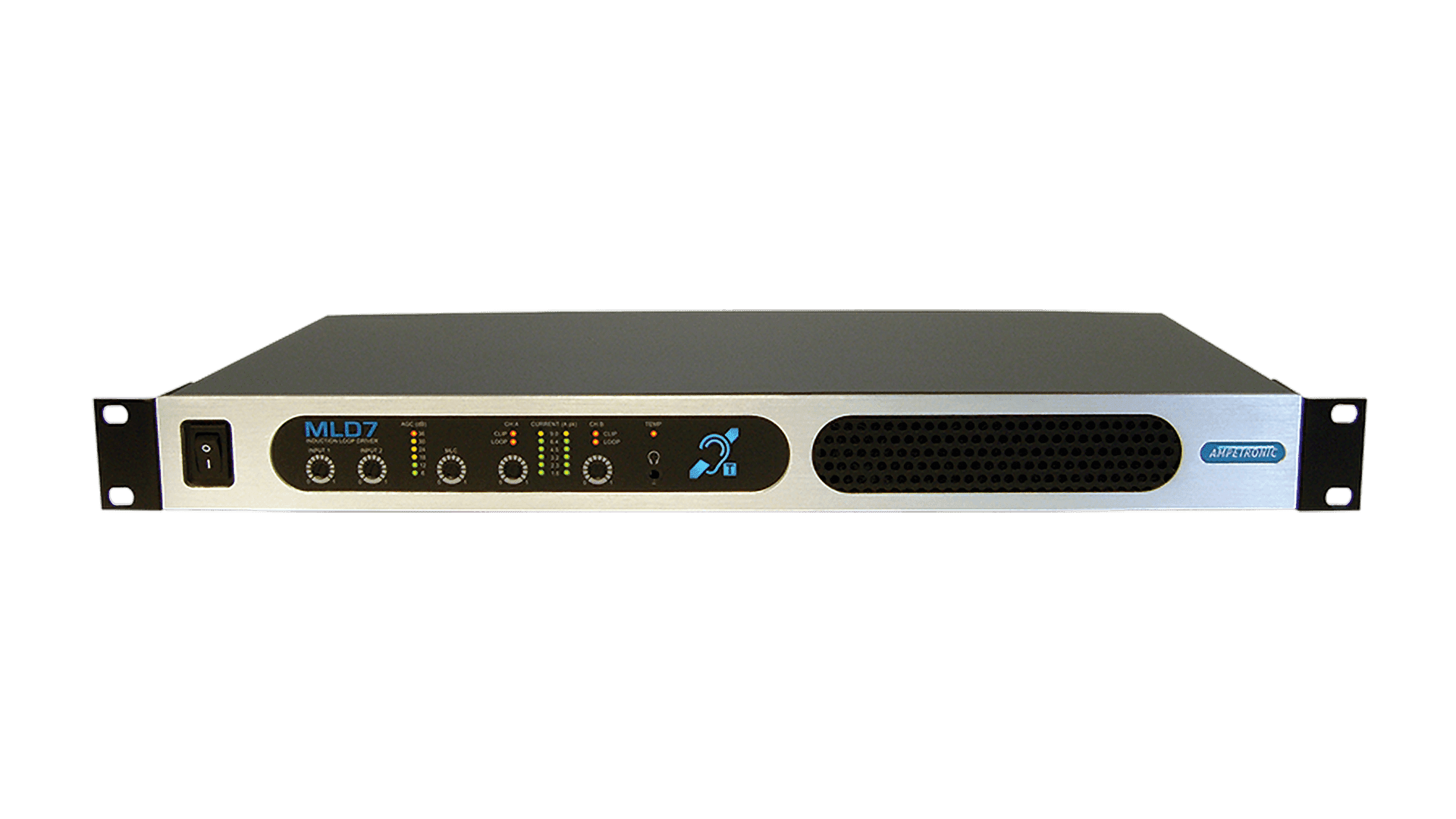
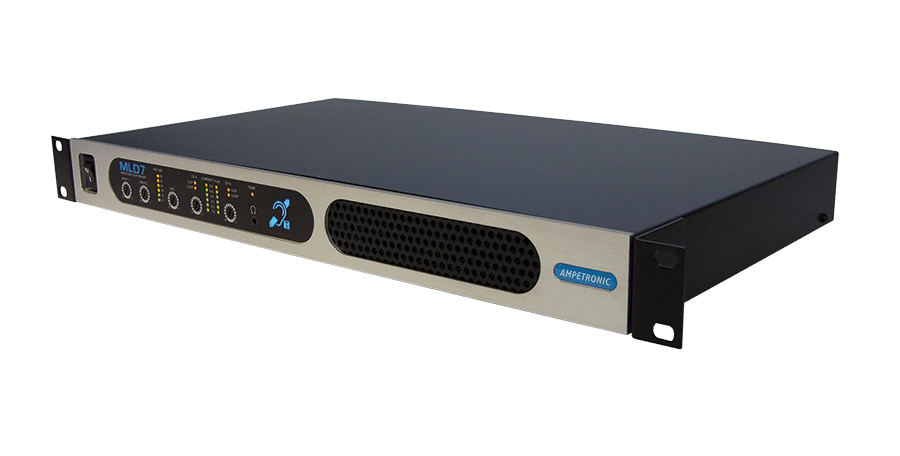
The MLD7 is part of the new benchmark range for professional audio induction loop systems. The elegant, sturdy units feature the most compact and most robust design on the market, requiring only a single 19” rack mount.
The MLD7 is capable of driving a wide variety of multiple loop configurations from multiple simple loops to phase shifted array systems for the most challenging requirements. With an Ampetronic MultiLoop™ Low Loss design, the MLD7 will drive an area up to 840m2, or can be used to drive two perimeter looped areas of up to 700m2 each.
Designed to provide optimum efficiency and ample current for Standard compliant field strength, coupled with unmatched voltage headroom to ensure crystal clear sound reproduction without clipping or distortion at practical loads. MLD units are built to our exacting standards and are backed by our 5 year warranty.
The flexibility of Ampetronic MLD units allows each output channel to drive separate loops, or two drive two overlaid loop patterns, with or without the selectable phase shift between the two channels.
Two separate simple area loops (or perimeter loops) can be driven at the same phase or with 90° phase shift. This can be used to cover large areas with no metal losses, or multiple different areas in the same facility.
Two loop layouts can be driven configured as multiple loop segments with or without phase shift. Simple array, low loss array or low spill array designs can create different performance to optimise field strength over any area, and minimise loop ‘spill’ for adjacent systems or for confidentiality.
Contact Ampetronic for free advice on all loop applications, design tools and support are available to check the expected performance for your application. Most commonly used design types are low loss and low spill:
Product Code:
MLD7
Loop Design | No Metal Loss* | Moderate Metal Loss** | High Metal Loss*** |
Low Loss | N/a | 300 | 170 |
Low Spill | 550 | 190 | 130 |
Perimeter Loop @ 1:1 Aspect Ratio | 2 x 400 | max 5m loop width | n/a |
Perimeter Loop @ 3:1 Aspect Ratio | 2 x 650 | max 5m loop width | n/a |
Typical scenarios are based on *a building with no structural metal, **a building with reinforced concrete (re-bar) construction.
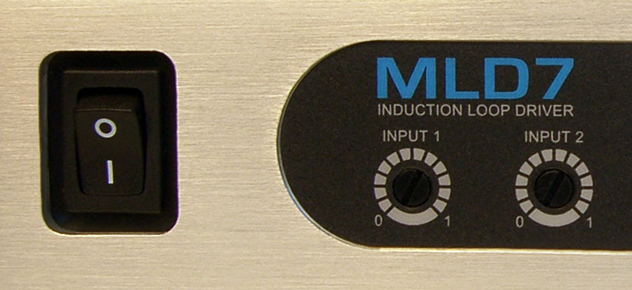
Power | 160W 230V AC nominal, 45-65Hz [120V option available] Power switch & LED indicator (Hearing Loop logo) on front panel |
Input 1 & 2 Programmable Microphone / Line | XLR balanced input with programmable 15dB gain boost switchable between microphone and line on the rear panel. Microphone specification; 200 – 600Ω, sensitivity -55dBu. Selectable 12V phantom power on microphone only Line sensitivity; -30dBu Screwdriver adjustable front panel recessed gain control |
Loop Output Drive Voltage | 17VRMS(24Vpk) at maximum output current per channel |
Loop Output | 6.4ARMS (9Apk) continuous 1kHz sine wave peak >9A per channel |
Drive Current | Cont. pink noise 3.2ARMS short term peaks >13A per channel Front panel recessed controls Drive current indicated on two 6-LED displays in 3dB increments |
Loop Connectors | Neutrik NL4 Speakons (supplied) for each output |
Loop Monitor | Provides access to monitor actual loop current via a 3.5mm stereo headphone connector on front panel Channel A on left, channel B on right |
Status | A pair of isolated relay contacts to indicate system status; fault = open circuit: system OK. = short circuit |
DC Output | Resettable, fuse protected 12V 0.1A. |
Idle | 1/6 peak Output Current (Speech) | 1/3 peak Output Current (Pink noise) | Full Power | ||||||||
Driver | Channels | Current (ARMS) | Load Resistance (Ohms) | AC In (W) | BTU | AC In (W) | BTU | AC In (W) | BTU | AC In (W) | BTU |
MLD9 | 2 | 9.2 | 1.5 | 25 | 85 | 100 | 293 | 210 | 524 | 560 | 1046 |
MLD7 | 2 | 6.4 | 1.5 | 25 | 85 | 92 | 291 | 160 | 454 | 330 | 711 |
MLD5 | 2 | 4.9 | 1.0 | 14 | 48 | 48 | 154 | 80 | 236 | 155 | 362 |
Frequency Response | 80Hz to 6.5kHz |
Distortion | THD+N <0.2% 1kHz sine at full current |
Automatic Gain Control | The AGC is optimised for speech. Dynamic range >36dB |
Metal Loss Correction | Corrects system frequency response due to metal structures in a building. Gain constant at 1kHz, adjustable gain slope from 0 to 3dB per octave. This does not compensate for signal loss from metal structures which can be significant. |
Phase Shift | User selectable at 0° or 90° between outputs |
Fault Monitoring | Fault indicators on the front panel: Clipping – delivering over the rated voltage (per channel) Temp – unit is too hot (temporarily mutes output signal) Loop error – short circuit / open circuit error (per channel) |
Status Contact | A pair of relay contacts are provided for remote fault monitoring |
Cooling | Twin variable speed fan cooled. Front inlet, rear exhaust. |
Size | Full width 1U 19″ rack mount. Width 430mm Depth 250mm Height 44mm |
Mounting Options | Freestanding 1U 19″ rack mount (brackets included) |
Weight | 4.77kg |
Environment | IP20 rated; 20 to 90% relative humidity; 0 to 35ºC |
Ampetronic can supply a range of accessories to meet the specific needs of your installation:
Input adaptors
By using the appropriate input adaptor or preamplifier the MLD7 will accept multiple additional inputs or audio inputs from other sources:
Input Type | Adaptor |
---|---|
100V line input Low impedance speaker line Line Level | ATT-UX transformer isolated attenuators |
Unbalanced microphones | MAT1 adaptor |
This product is designed to form part of a system that can meet all of the requirements of the international loop performance standard IEC60118-4, and the relevant parts of BS7594. To fully meet requirements of these standards, correct design, installation, commissioning and maintenance are required.
All specification data has been compiled in accordance with IEC62489-1, the international standard for audio frequency induction loop equipment. Specification data should only be compared with data compliant to this standard.
This product is CE market to all relevant safety and EMC standards, and is NRTL(ETL) approved for sale in North America.
For detailed information on approvals, standards compliance and how to interpret the technical parameters on Ampetronic datasheets, please visit the support section of our website or contact support@ampetronic.com.