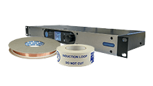
This tool allows you to work out the output current setting needed on your Ampetronic loop driver to achieve a specific RMS current in the loop.
You can also use it the other way round by entering a target RMS loop current and finding out the correct output current setting for your driver.
This can be useful in several scenarios.
If performing metal loss testing for example then often a 2.5A sine wave test signal is used, this allows you to quickly configure your driver to the right output setting.
If troubleshooting a loop installation, measuring the current in the loop with a digital multimeter can help determine that the system is performing as expected. Measuring a lower current than the driver and output settings should generate can indicate a fault with the loop wiring such as a short to ground.
Pay close attention to the signal type used, pink noise will produce half the current for a given driver output setting in comparison to a sine wave. If using a combi signal you should see the current change back and forth between the pink noise and sine wave levels.
NEW C Series C10-1, C10-2 and C14-2 drivers now available
Click here for details

We offer free advice and guidance to all of our customers on any subject related to induction loops and assistive listening systems.
Our information centre also contains a great deal of useful material. If the website does not answer your questions please contact us by phone, email or talk to us through Live Chat.
We will endeavour to respond to any enquiry within 1 working day.
Telephone: +44 (0) 1636 610062
Email: support@ampetronic.com
or click here to chat live* with our support team
*during UK office hours: 08:30 - 17:30 (GMT/UTC), Monday - Friday


