With the close of 2021 leaving us with a stark message from the COP 26 global summit that, despite all the pledges from every nation around the world, we are still coming up short of our targets of limiting global warming to an increase of 1.5°C. As the events of early 2022 plunge Europe at least into an energy crisis with spiralling costs across the board, it is clear that we must endeavour to avoid wasted power and attempt to minimise energy usage in every aspect of our lives.
Induction Loop Drivers are no exception, and in the same way that in the last 20 years all digital electronic devices have reduced in size, increased processing power and become more efficient, the same technological advances have enabled complex audio power amplifiers to become little more than ‘System on Chip’ solutions – with very few external components. This has made the switch to Class D or digital loop drivers a viable option, and the benefits can be significant.
Driving an induction loop is very much like driving a speaker, aside from the fact that for a loop the current is regulated to control the magnetic field produced, and the loop can be a range of lengths whereas a speaker is usually a defined impedance. These two subtle differences present a problem when designing a Class D loop driver to be both stable and meet EMC requirements – I won’t go into the technicalities here, so let’s focus on the benefits once these challenges have been overcome.
In terms of electrical analysis, the model of an induction loop is comprised of two main components, a resistance and an inductance. Any capacitance is small enough not to be significant at audio frequencies. An ideal resistor is a simple element in which the current is perfectly in phase with the voltage across it. For ideal capacitance and inductances, the term “CIVIL” reminds us whether the current is 90° (quarter of a cycle) before or 90° after the voltage across it. For example, at 1kHz:
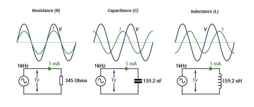
Figure 1
In practical terms, there are two very significant points to note
- The maximum current in a capacitor or an inductor coincides with when the voltage is zero. We’ll come on to the implications of that in due course.
- The second takes a little more explanation – due to this phase shift, power is only dissipated (lost) in the resistor. The lesson here is to reduce the resistance as much as possible – a superconducting loop (zero resistance) would lose no power, but that is not practical.
In terms of point 2, and comparing a resistor and an inductor, we can show how power is cancelled over one complete cycle using the formula:
P = V x I (Power = Voltage x Current)
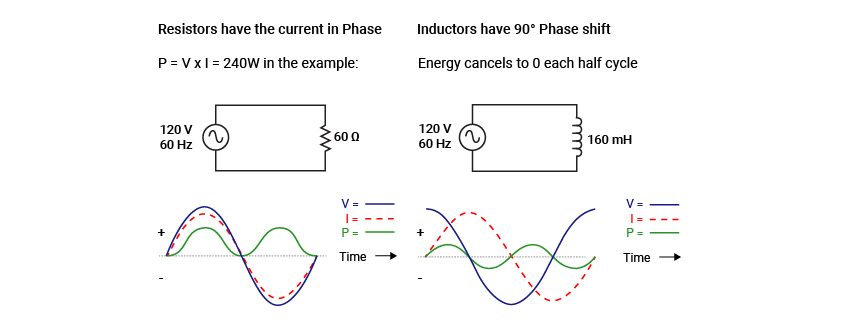
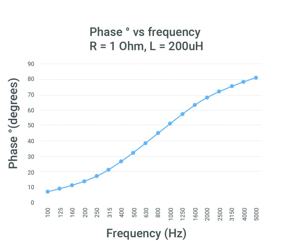
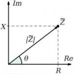
Coming back to point 1 – when we drive a loop which comprises of predominantly resistance and inductance, the phase shift between the current will sit somewhere between 0 and 90° depending on the relative magnitude of the two (R and L) elements at the signal frequency we are running.
Phase shift between Voltage and Current in real loop load:

In real terms, any current into a load must be delivered from an internal power supply in a product. This will be either an internal single or dual ± power supply rail depending on the product, but the same principles apply in either case.
Considering different classes of Power Amplifier (PA) output stage it is possible to see the impact of driving a loop comprising of resistance and inductance and determine when and how power loss is increased.
Class AB is a PA topology which has at least one power device (transistor) that is always on, but never fully. This device delivers the current from a supply rail and bridges the voltage difference between the rail and the output - dependant on load, frequency, rail size and part of the cycle etc. The voltage difference may be large and even opposite polarity in the case of reactive loads!
This means that with smaller loads (and reactive loads at higher frequencies) we have a lower voltage in the loop (or even opposite polarity) in comparison to the fixed supply voltage and therefore more power wasted (or heat) in the amplifier. The dissipation in the power devices is made worse by:
a. Higher supply rails
b. Increased current delivery
c. Increased phase shift between the voltage and current – directly increases the voltage difference between the supply rail and the voltage output.
Class G / H are similar PA topologies which involve using a pair of power supply rails for each polarity and as such are well suited to high voltage output stages driving loads which present a significant phase shift – i.e. induction loops.
With a highly inductive load and a larger phase shift, the peaks of the current are delivered from the lower rails which translates to a large power saving.
Ultimately this is a work around for Class AB which reduces the impact but does not change the underlying issues – the same factors influence power dissipation, just to a lesser extent.
Class D is a topology which is essentially digital and involves the program material being turned into a high frequency switching (PWM) signal. Once this signal is scaled in terms of Voltage and Current it is subsequently filtered to remove the switching signal before being connected to the load - hence the need to manage the EMC requirements as part of the process.
While there are some switching losses and heat in the output filter whenever we run current the amount is not related to what load is applied, only what current is delivered. This means that internal power dissipation is a much smaller issue and known. We don’t waste anywhere near so much as heat in the amplifier (hence also Class D being more efficient and not running as hot (see the Ampetronic loop driver thermal heat chart). The actual power required is down to the current needed and the resistance of the load (I²R), so much less power is used (total by the amplifier) when running into smaller loads; unlike Class A/B where the power required is fixed for a given current.
As the power devices (transistors) are either ON (very low resistance) or OFF, the power requirements of any system related only to:
a. current delivery
b. load resistance
There is no major penalty for high supply rails, only the ability to deliver this if required. Therefore, with Class D amplifier design you need to allow for enough power to deliver the stated current into a sensible maximum resistive load. This could be done based on using max cable length and 0.5mm² cable, but it would be very expensive and a waste for most real-world applications, so it’s generally designed around using the larger cable sizes available, when trying to deliver full current and a high cable length.
This is where the power limit in Loopworks comes in, showing when the resistive load is too high for the given current. The easy way to account for this is to decrease the resistive load by using a larger cable size (3mm² tape, or 2.5mm²/4mm² wire).
Finally, we have protection circuits to apply sensible power limits. This is to ensure that even if the unit is connected to an 8 Ohm load - it is prevented from delivering power levels beyond its capability. Aside from potentially limiting against supply rails, the output stage may be quite happy to deliver this level of power - but the input transformer is not capable of supplying it long term, and would thermally or current limit with inbuilt fusing.
In some cases, this means that the Class D amplifiers can’t deliver the same current into the same load as the equivalent Class A/B or G/H amplifier, however these previous models were expensive to make as their inefficiencies had to be accommodated. With the Class D we can make a sensible decision about that power limit to balance performance against cost, which allows us to provide these amplifiers for the same or cheaper cost than the equivalents, with a whole host of other new features included.
In the cases where the power limit is an issue, a larger conductor overcomes this and puts them back in the same position performance wise as they would have been with the Class A/B or G/H. As explained above, that same change in cable choice would have very little impact on the Class A/B or G/H drivers.
But what does it all mean in reality?
The biggest savings in terms of power are with sinewave signals which, unless the program material is orchestral, is unlikely to be reality. In terms of power capability, any loop driver must be able to deliver continuous pink noise to enable the field strength and frequency response to be measured (ref IEC 62489-1), as well as providing for periods of high RMS signal content, but most loop installations are providing speech content in assistive listening applications. Here is how the relative input and output powers stack up for Perimeter and Multi-loop applications:
The benefits of Class D hearing loop amplifiers

What is noticeable here is that whatever signal type the ‘Load’ power is largely the same, but the ‘Input’ power is markedly lower for the C-Series Class D solutions than their Class A/B equivalents. This holds true even for speech signals and although the power saving is less in relative terms the percentage comparison is far lower.
On top of this there is an added un-seen benefit available to Class D drivers, i.e. it is possible, during long periods of no signal, that the PWM signal can be shut down, putting the unit into a power saving or standby mode. If a unit is only running for 8 hours a day it can save further power when not being used and be triggered by the presence of input signal to return to action as and when the service is required.
Based on running for 8 hours a day for speech and 16 hours of standby, it is a simple exercise to demonstrate the monetary value of using more efficient topologies with ever changing cost of energy.
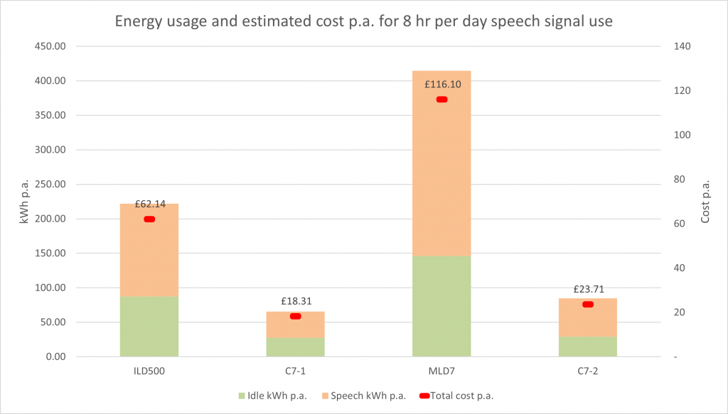
(based on £0.28/kWh (forecast average UK price as of March 2022)
The added benefit of a less power-hungry system means there less impact on moving parts such as fans, in some cases removing the need for them entirely. Generally cooler systems maintain a longer life expectancy for thermally sensitive items such as electrolytic capacitors.
Conclusion
Altogether the Class D solution is perfectly suited to drive induction loops but the benefits cannot be fully realised unless the design and configuration of the system are carefully considered. Alongside other features such as semi-automated set-up using Loopworks Looplink over a local IP network, saving significant installation time (see "The benefits of networked amplifiers" by Andrew Attard), remote monitoring and integration with other Pro-AV systems such as DANTE, Class D drivers from Ampetronic are a great way to take advantage of energy savings and make the world a little cooler than it was yesterday!
NEW C Series Class D networkable drivers now available
Click here for details

Russell Simpson
Technical Director
Russell joined Ampetronic in 1996, after completing a BEng in Electrical and Electronic Engineering at Nottingham University.
He has over 25 years experience of developing class leading technology and solutions for assistive listening.
Russell is a UK representative for IEC TC29 committee on Electroacoustics, and plays a prominent role in the development of standards related to induction loop systems.
A keen musician, sport & technology enthusiast, but most of all a problem solver, Russell has some empathy with the hearing impaired as he experiences minor hearing loss in one ear; however his motivation for working within the industry is really to help people to communicate by providing great products and services.

