

Site testing prior to specification of a hearing loop
Site testing for electromagnetic background noise and metal in a buildings construction should be performed prior to the specification of any induction loop system. If present both these factors will have an effect on loop design, driver selection and very occasionally whether or not the project is actually feasible.
See HLS-2D Metal Loss Test Driver
Metal construction is likely to have been used in almost all modern commercial buildings or large structures, often in the form of metal framework or concrete reinforcement (rebar). Buildings with significant amounts of metal in their construction will require a phased array loop design and powerful amplifier(s).
Electromagnetic background noise is often caused by lighting fixtures or nearby electrical transformers, however in many cases it is due to faulty wiring, which can be corrected.
Testing Electromagnetic Background Noise
Using a Field Strength Meter (FSM), hold the device in a vertical position to align the telecoil with the component of the magnetic field you are testing and set the selector switch to the background noise setting.
An acceptable reading that will not affect the performance of an induction loop is less than 32dB and it is essential that the reading be less the 22dB.
Readings should be taken throughout the area that the loop will cover to pinpoint any localised magnetic background noise.
Here is a video example:
Testing for Metal Using a Test Loop
Once it has been determined that it is an acceptable environment for an induction loop system but it is suspected or known that the building construction features metal, a test loop should be laid to determine the effects of metal loss on the magnetic field and to allow for an accurate specification of the required system.
This is done by constructing a figure of 8 test loop of even section widths and typically using an ILD500 or ILD1000G amplifier to cover a range of applications.
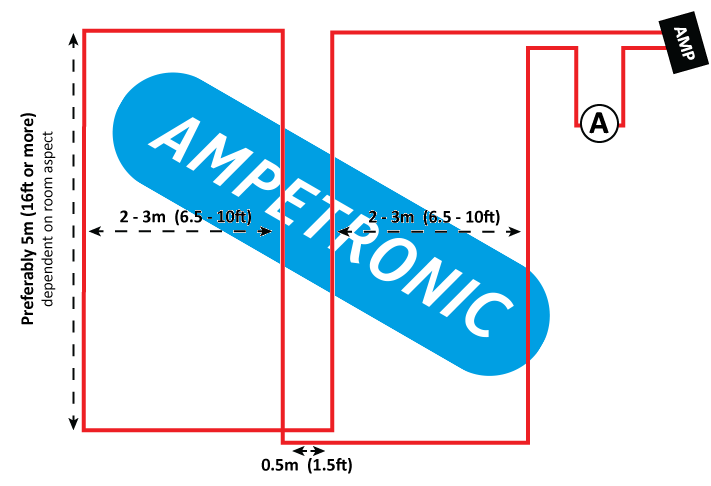
Each loop section should be between 2 to 3 meters (6.5 and 10ft), and the field strength within this is tested in a number of positions. An ammeter should be placed in series with the loop to determine the base current through the system.
This data is then collected and compared to a simulation performed by Ampetronic or an Ampetronic authorised distributor, which allows us to determine the amount of metal loss inherent in the system specific to that environment.
The diagram above shows a typical figure of 8 test loop the widths of which are usually 6.5 – 10ft which is indicative of typical phased array installation.
