

Commissioning an Induction Loop System
All induction loops should be commissioned post installation to ensure that they comply with the IEC 60118-4 Standard for performance. This task is often performed by the installing engineer; however consultants or even Ampetronic’s engineers may be required on very complex projects.
The commissioning procedure is designed to identify and rectify any faults in a system and provide the opportunity to address them. When the system is deemed to be operating to Standard the commissioning engineer should fill in and present a Certificate of Conformity to the facility owner/manager.
The following is a brief summary of what is required to commission an induction loop system, to access full details of the procedure of how to perform and record it please consider our 1day practical installer training courses or signing up to one of our webinars.
Commission Procedure Overview
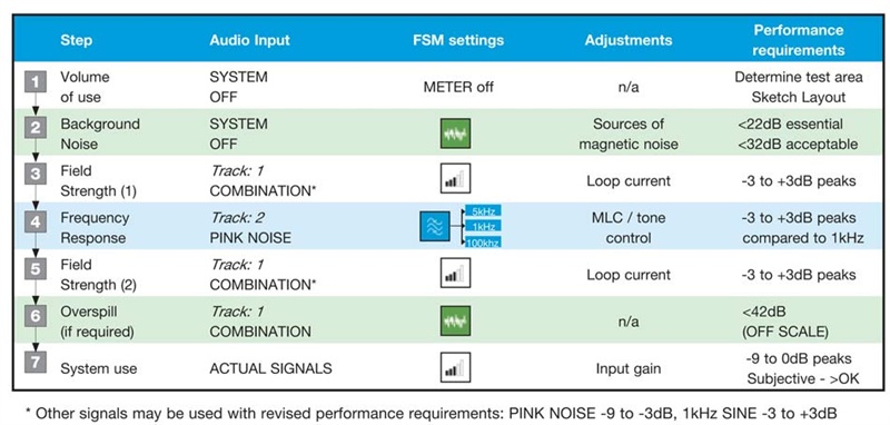
In order for an Induction Loop System to be certified as compliant with the IEC 60118-4 standard it must be tested for the following using a Field Strength Meter or CMR3 connected to a compatible audio analyser, the results of which should be detailed on the ‘Certificate of Test and Conformity’:
- Volume of use.
The area that the loop covers should be defined and the intended use identified. If the intended audience could potentially be both seated and standing measurements will be required at both heights. - Background noise
Magnetic background Noise: -32dB or better (A-weighted). Background noise should not affect intelligibility. - Field strength
Filed Strength 400mA/m sine wave @ 1kHz, ± 3dB over the listening area to ensure that the listening volume is neither too quiet or too loud to overload the hearing aid and remains constant whilst moving around the area covered by the loop. - Frequency response
100Hz – 5kHz ± 3dB ref. level @ 1kHz Must be maintained across coverage area. This is essential for the system to reproduce all frequencies required for human speech and thus maintaining intelligibility. - Overspill & live signals
If the system is to be installed close to other induction loop systems it is imperative that the signal spill is measured and marked on the area coverage map to mitigate interference. If confidentiality is an issue the distance from the loop at which the signal becomes inaudible should also be recorded. - Signage & indication of area coverage
Signage should be included in any commercial installation; a user should not have to ask. International standard induction loop signage should be clearly visible within the room, and preferably on each entrance.
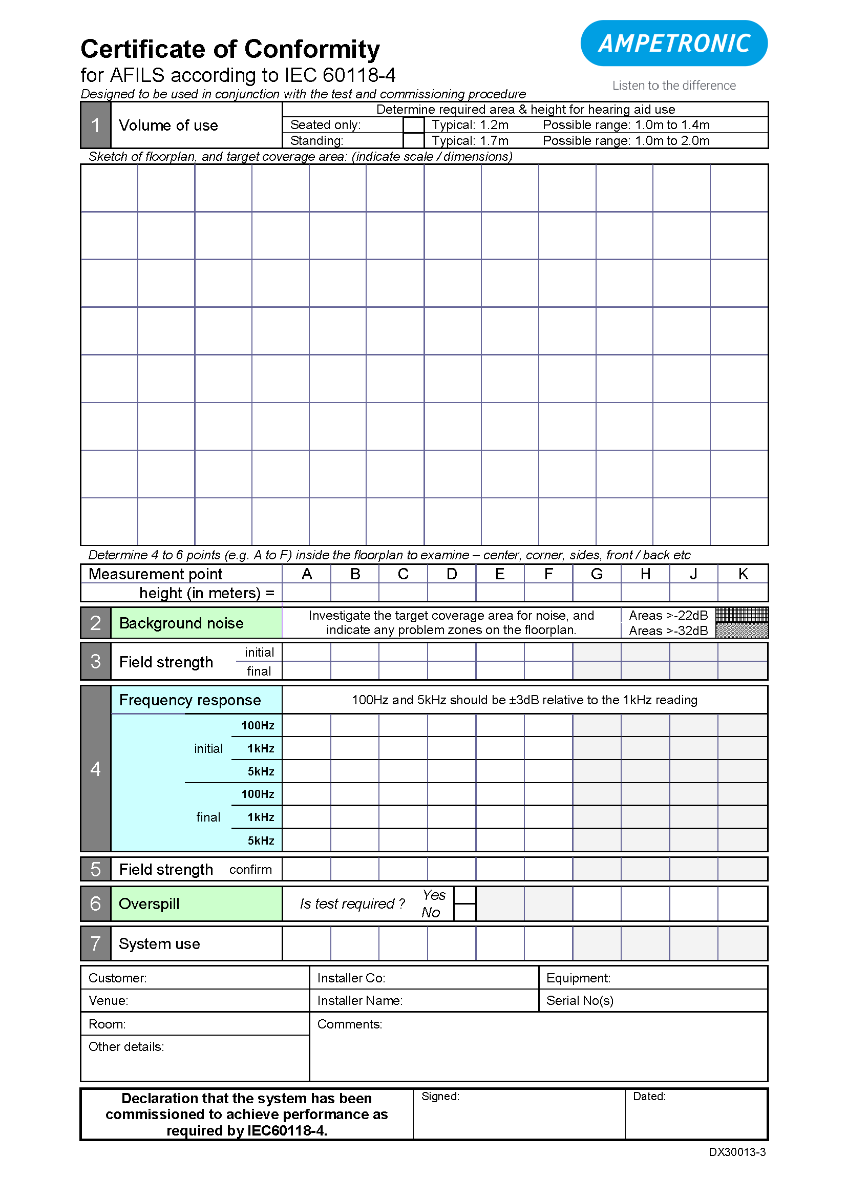
The certificate should show measurements taken in several areas of the loop; if a low spill system is installed measurements should be taken from an acceptable distance outside of the looped area.
Diagrams should be constructed showing measured areas within the loop and any areas which fall outside of standard (for example background noise due to electromagnetic interference such as transformers etc.)
The frequency response of the loop system in relation to a pink noise signal should be measured referencing a number of different frequencies (100 Hz – 5 kHz) 100Hz & 5kHz should be ±3dB relative to the 1kHz reading. With typical speech and transient signals such as music you will find the signal is -9 - 0dB (peak) as opposed to -3dB – + 3dB
Commissioning certificate should be handed over to the end client along with an adequate number of loop receivers and usage instructions.
